Experiment Load Angle vs Power Factor
 |
| Experiment load angle(δ) VS power factor(Φ)[figure 1] |
Introduction
This is actually a mathematical experiment of Synchronous Generator we are trying to show what effect the change in Load angle will have on the different power factor (lagging and leading) and vice-versa.Constant Data
At first we take some assumed value of synchronous generator.
Line voltage (VL)= 250 V
So, Phase voltage (Vp)=250/√3=144.3 V
Armature resistance (Ra)=0.8 ohm
Synchronous reactance (Xs)=1.5 ohm
Synchronous impedance (Zs)=0.8+j1.5=1.7∠61.92°
Power rating of Synchronous Generator(P)= 12 KVA
P=√3 VL IL
load current IL= P/√3 VL
So,IL=((12×103)/(√3×250))=27.71 A
Vp =144.3∠0°
Zs=1.7∠61.92°
We are take Power Factor 0.8 and 0.9 lagging and leading both
When Power Factor lagging then use 0.8 and 0.9 and record the Vp and δ
And power factor leading then use 0.8 and 0.9 and record the Vp and δ
Lagging
Power factor 0.8
Ip=27.71∠-cos-1 0.8
=27.72∠-36.86° A
Ep=Vp+Ip Zs
=144.3+(27.71∠-36.86°)×(1.7∠61.92°)
=144.3+42.67+j19.95
 |
| Experiment load angle(δ) VS power factor(Φ) [figure 2] |
=186.97+j19.95
=188.03∠6.09° V
Power factor 0.9
Ip=27.71∠-cos-1 0.9
=27.72∠-25.84° A
Ep=Vp+Ip Zs
=144.3+(27.71∠-25.84°)×(1.7∠61.92°)
=144.3+38.07+j27.74
 |
| Experiment load angle(δ) VS power factor(Φ)[figure 3] |
=182.37+j27.74
=184.46∠ 8.64° V
Leading
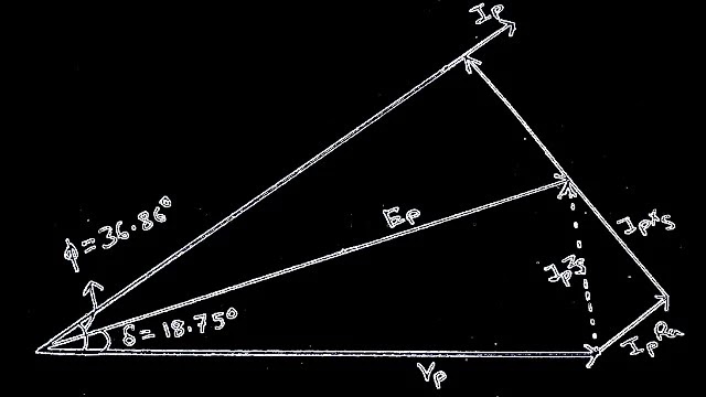
Power factor 0.8
Ip=27.71∠cos-1 0.8
=27.72∠36.86° A
Ep=Vp+Ip Zs
=144.3+(27.71∠36.86°)×(1.7∠61.92°)
=144.3-7.19+j46.55
 |
| Experiment load angle(δ) VS power factor(Φ)[ figure 4] |
=137.11+j46.55
=144.76∠ 18.75° V
Power factor 0.9
Ip=27.71∠cos-1 0.9
=27.72∠25.84° A
Ep=Vp+Ip Zs
=144.3+(27.71∠25.84°)×(1.7∠61.92°)
=144.3+1.8+j47.07
=146.1+j 47.07
=153.49∠ 17.85° V

Experiment load angle(δ) VS power factor(Φ)[ figure 5]

Data Sheet
Next sheet states that We see that when primary voltage decreases the load angle increasing order at the power factor 0.8 (lagging)
And second result states that when primary voltage increases the load decreasing order at power factor 0.9 (leading)
Conclusion
This is a Theoretical Experiment with Load angle vs power factor. This Experiment essentially applied in many generating stations . This Experiment helps the governor settings of alternator.
--------------------------------------------------
Other posts


![[PDF] Competitive Exam MCQ For Electrical Engineering](https://4.bp.blogspot.com/-O3EpVMWcoKw/WxY6-6I4--I/AAAAAAAAB2s/KzC0FqUQtkMdw7VzT6oOR_8vbZO6EJc-ACK4BGAYYCw/w100/nth.png)


0 Comments